Carton Packing For Bopp Thermal Film And Soft Touch Film
Homemade Van De Graaff Generator
by:Top-In
2020-07-16
Triboelectric series * furniture roller (see step 3)
*~ 2 inch od pvc pipe (1 1/2 inch ID)
* 4 inch id pvc tube-2-
3 feet long * 4 inch mounting flange * 4 inch connector * steel bar for axle * skateboard bearing, or other sealed bearings * electronic perf board or circuit board * stick pin * light dimmer switch * 120 v ac Toggle switch (
May be optional, see Step 2)
* Fuse holder * AC electric sewing machine engine or other 1/8 to 1/2 hp AC engine * output terminal (
Stainless steel sightseeing ball, liquid helium tank or other metal ball * nuts, bolts, screws, etc.
On both of my larger units, I used the recycled sewing machine engine to drive the unit.
This arrangement creates a direct drive that simplifies the build process.
If you don\'t have or can\'t find the AC motor, then you can choose the AC motor and use the pulley device to drive the lower roller.
I am not very interested in this step because the base I use does not have enough space to install the motor, so it is connected to the lower side of the base with a gasket.
The disadvantage of this is that the adjustment is limited and the motor vibration will spread to the whole equipment.
Maybe when I rebuild the base I will install it on the spring loaded platform.
Control the motor speed using a standard light dimmer switch.
You should connect it first to see if it starts with the highest voltage or the lowest voltage.
If it starts at the highest point, you need to add an on/off switch when you start to avoid tightening the belt and bearing, and set the dimmer to the lowest setting.
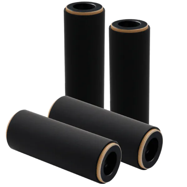
The lower rollers come from a set of furniture rollers with an OD of 1 5/8 \".
Drilled the center hole and I had to zoom in the hole a little and slide it onto the motor shaft with some alcohol.
Once the alcohol evaporates, this installs the rollers permanently on the shaft.
In addition, this Roller has a slight top, which is desirable as it can help the belt to maintain a straight line during operation.
The upper roller is a 2 3/4 \"long section 2\" white PVC pipe with a diameter of 2.
Two skateboard wheels are used as the central hub of the upper roller.
I fixed them together with bolts, mounted them on the drill press, and then sanded them with sandpaper until they were firmly pressed on the PVC pipe.
The rollers are placed in the Chuck bracket of the lathe and the ends are polished to give the center a crown.
The bearing is inserted into the wheel in the roller, the shaft passes through the center hole of the roller and comes with a locking ring to keep the roller centered and the shaft is mounted in the bearing at each end.
See the picture for more details.
Base is connected by 2-19.
75 \"2x4 to 21.
5 \"take 12\" pieces of broken material board.
One end is closed by 12 \"2x4.
The other end is a particle board with a switch.
To prevent moisture absorption, acrylic or other plastic building materials are recommended by most people.
If you choose to use a wood or scrap board, one or two layers of polyurethane should be able to cover it well to prevent moisture problems.
There is a hole in the deck, the belt can pass through, and a PVC closet mounting flange is installed on the deck.
The column is a 4 \"diameter PVC pipe from the hardware/Home Center for sale in a pre-cut 2\' length.
You can cut it yourself, but you need to be able to make the end Square so that the post does not tilt to one side or the other, as this will be jogging to one side at a high speed off the trail and making the belt.
There is not much wiring necessary.
Connect the dimmer switch and fuse holder in series with the hot side of the AC power cord.
The main service functions of the support column are: 1.
Separate the upper and lower rollers. 2.
Output terminal is supported.
Support columns should be selected to allow sufficient clearance for the belt.
The height part of the column depends on the size of the output terminal;
The general rule is that the distance between rollers should be at least 1.
5 times the diameter of the output terminal.
Therefore, for an output sphere with a diameter of 12 inch, there should be at least 18 inch between the rollers.
In my unit, I used a pre-
Cut the length of the PVC 2 feet to make sure I am using the square end as I do not have a reliable way to do a square cut on the PVC.
When you increase the distance between the upper connector and the roller assembly, and the distance it passes through the base to the motor, it almost adds another foot.
Therefore, in this unit, the distance between the rollers may be twice the ideal length.
A shorter column would be better to reduce the cost loss, but I have to work with my stuff.
If you can use an electric herringbone saw, or you have an electric PVCtube cutter in your local home goods store that can cut square ends, then you can cut them according to your specific needs
Secondly, the inlet holes on the output end will be installed on the 4 inch PVC pipe and stay on the coupler that connects the support column to the roller assembly.
The inner sleeve has a ring that inhibits the corona to reduce the corona discharge, and the sleeve itself helps to stabilize the output terminals on the support column.
This part may be the hardest step, but it is a crucial step for a successful build.
I tried a lot of different belt material, some didn\'t work, some didn\'t work, but it was tedious to make.
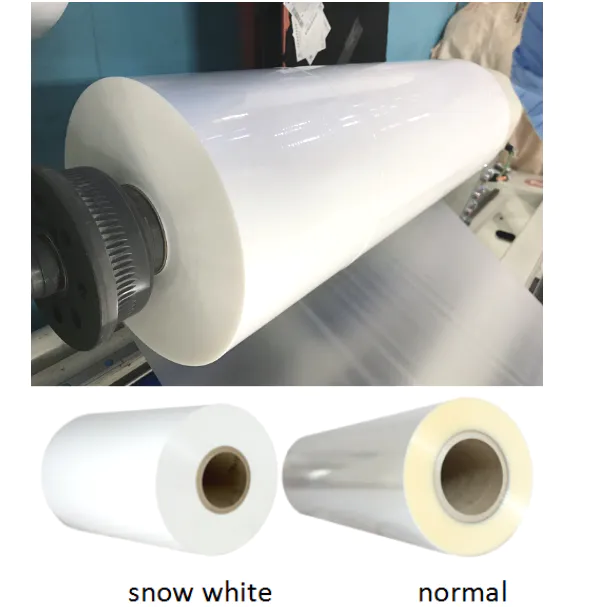
The two materials that are easiest to use are moving rubber bands or plain roller shadow materials.
If you ask your local hardware store, they may be willing to cut the pieces for you or sell them to you, as most stores usually discard them.
The rubber belt will provide the best charging current in both, but will be affected by stretching or lifting at a higher speed, which will cause problems of keeping track properly.
The rubber belt material is also hard to cut straight because it stretches even with a very sharp blade, so you have to take a moment and be extra careful.
I found it easier to flatten the material, make a line with the straight edge, and then wire along this line with a ruler and razor.
It\'s always the best to have a square (factory)
To make sure your belt is straight, the roller shadow material does not provide that much charging current, but can run at a higher speed once \"broken\" without lifting or tracking
Roller shadow material is easier to cut because it does not stretch when cutting and can be cut with a rotary craft knife or scissors.
In any case, the belt should be narrower than the roller.
For example, if your roller is 2 inch wider than you should have a belt that does not exceed 3/4.
Keep in mind that when the rubber band is used, the width is reduced by about 1/4 to 1/3 when in tension, so cutting to be smaller or narrower than the roller.
Also, you have to stitch the ends together at a certain angle, because if they are cut into squares, they cross the roller and eventually damage the bearing.
In previous builds, I have spliced the end at a 45 degree angle.
But I \'ve recently read how others use V and inverted V to splice them, which makes the center of the belt go through the roller at the splicing and distribute evenly out on the roller.
I found that there are two products that are the best to fix the belt on yourself.
The best glue I found for the rubber band is greatglue.
A product called vinyl welder.
I would suggest allowing the adhesive 18-
Heal 24 hours before using the belt.
If you choose to install the motor on the adjustable platform, you can make adjustments there, or make a spring-mounted upper roller assembly like I adjust the tracking.
Alternatively, if you want to install the bearing inside the hub, you can simply cut the slot along the side of the PVC column (
As shown in the last picture)
Use threaded shaft, fix shaft with locknuts.
The comb squirts the charge onto the belt at the bottom and pulls the charge off the belt at the top.
They can simply strip off some of the stranded wires and spread out individual stocks as shown on the desktop VDG.
You can make them with stick pins and perfboard, or salvage pieces from other devices, as in the third picture.
This is the metal strip removed from the dispensing machine.
When designing the bracket, you should provide a way to change the distance of the comb to the roller.
It is also desirable to be able to move the comb around the roller.
I found the comb most effective at or near the separation point.
Others say the best thing is to be directly above the top roller and directly below the bottom roller.
Again, the experiment will determine the best place to build.
The output terminals are usually a large hollow ball body, but the recycled helium tank I use in this project can use other shapes.
The main thing is that it should have a smooth surface to reduce the leakage of the corona, and there is no sharp turn or angle that may be drawn from the charge.
The problem with metal balls is that they are expensive! ! .
For less than $60, you can have up to 12 \"spheres \".
But if it is bigger, the price will rise.
Search for stainless steel sightseeing balls and you will find that you can pay $165 for a sightseeing ball with a diameter of 20. 00 to $240. 00 online;
And 24 balls will reach $1000. 00 range.
For smaller units, 8 \"metal plastic decorative balls can be used, as shown in the third picture.
If you look around the holidays, you can buy these for £ 50% --
75% of the original price.
Another option that people try is to connect the two stainless steel bowls together and attach tape to the edges to reduce corona discharge.
This can be a very cheap way because the bowl doesn\'t need high quality and if you make a mistake, cut the entrance holes for $2. 00-$3.
The 00 bowl is not as devastating as $30. 00-$50.
Once you have the output terminal, the next step is to create the entrance hole, because the charge must be applied to the inside of the sphere in order to get a higher voltage.
I recommend cutting stainless steel using a Angle grinder or a cutting wheel to make an inlet hole.
I would suggest not to have a jigsaw puzzle because the vibration may break the sphere.
The ideal shape is for the side of the inlet hole curve to extend up into the sphere, but the stainless steel is not plastic, and if bent to a certain extent, it will fold and fasten.
Therefore, the use of the corona ring is strongly recommended.
It\'s just a soft copper, welded or pressed-fit ring around the entrance hole like I did.
The ring significantly reduces the corona leakage at the entrance hole and allows the output terminal to charge to a higher potential.
These photos were taken in 5 under normal lighting conditions.
1 million pixel digital camera.
I got the generator running and just started clicking and there are some photos that don\'t show any sparks but I think they are a bit cool and would like to share with you all.
*~ 2 inch od pvc pipe (1 1/2 inch ID)
* 4 inch id pvc tube-2-
3 feet long * 4 inch mounting flange * 4 inch connector * steel bar for axle * skateboard bearing, or other sealed bearings * electronic perf board or circuit board * stick pin * light dimmer switch * 120 v ac Toggle switch (
May be optional, see Step 2)
* Fuse holder * AC electric sewing machine engine or other 1/8 to 1/2 hp AC engine * output terminal (
Stainless steel sightseeing ball, liquid helium tank or other metal ball * nuts, bolts, screws, etc.
On both of my larger units, I used the recycled sewing machine engine to drive the unit.
This arrangement creates a direct drive that simplifies the build process.
If you don\'t have or can\'t find the AC motor, then you can choose the AC motor and use the pulley device to drive the lower roller.
I am not very interested in this step because the base I use does not have enough space to install the motor, so it is connected to the lower side of the base with a gasket.
The disadvantage of this is that the adjustment is limited and the motor vibration will spread to the whole equipment.
Maybe when I rebuild the base I will install it on the spring loaded platform.
Control the motor speed using a standard light dimmer switch.
You should connect it first to see if it starts with the highest voltage or the lowest voltage.
If it starts at the highest point, you need to add an on/off switch when you start to avoid tightening the belt and bearing, and set the dimmer to the lowest setting.
The lower rollers come from a set of furniture rollers with an OD of 1 5/8 \".
Drilled the center hole and I had to zoom in the hole a little and slide it onto the motor shaft with some alcohol.
Once the alcohol evaporates, this installs the rollers permanently on the shaft.
In addition, this Roller has a slight top, which is desirable as it can help the belt to maintain a straight line during operation.
The upper roller is a 2 3/4 \"long section 2\" white PVC pipe with a diameter of 2.
Two skateboard wheels are used as the central hub of the upper roller.
I fixed them together with bolts, mounted them on the drill press, and then sanded them with sandpaper until they were firmly pressed on the PVC pipe.
The rollers are placed in the Chuck bracket of the lathe and the ends are polished to give the center a crown.
The bearing is inserted into the wheel in the roller, the shaft passes through the center hole of the roller and comes with a locking ring to keep the roller centered and the shaft is mounted in the bearing at each end.
See the picture for more details.
Base is connected by 2-19.
75 \"2x4 to 21.
5 \"take 12\" pieces of broken material board.
One end is closed by 12 \"2x4.
The other end is a particle board with a switch.
To prevent moisture absorption, acrylic or other plastic building materials are recommended by most people.
If you choose to use a wood or scrap board, one or two layers of polyurethane should be able to cover it well to prevent moisture problems.
There is a hole in the deck, the belt can pass through, and a PVC closet mounting flange is installed on the deck.
The column is a 4 \"diameter PVC pipe from the hardware/Home Center for sale in a pre-cut 2\' length.
You can cut it yourself, but you need to be able to make the end Square so that the post does not tilt to one side or the other, as this will be jogging to one side at a high speed off the trail and making the belt.
There is not much wiring necessary.
Connect the dimmer switch and fuse holder in series with the hot side of the AC power cord.
The main service functions of the support column are: 1.
Separate the upper and lower rollers. 2.
Output terminal is supported.
Support columns should be selected to allow sufficient clearance for the belt.
The height part of the column depends on the size of the output terminal;
The general rule is that the distance between rollers should be at least 1.
5 times the diameter of the output terminal.
Therefore, for an output sphere with a diameter of 12 inch, there should be at least 18 inch between the rollers.
In my unit, I used a pre-
Cut the length of the PVC 2 feet to make sure I am using the square end as I do not have a reliable way to do a square cut on the PVC.
When you increase the distance between the upper connector and the roller assembly, and the distance it passes through the base to the motor, it almost adds another foot.
Therefore, in this unit, the distance between the rollers may be twice the ideal length.
A shorter column would be better to reduce the cost loss, but I have to work with my stuff.
If you can use an electric herringbone saw, or you have an electric PVCtube cutter in your local home goods store that can cut square ends, then you can cut them according to your specific needs
Secondly, the inlet holes on the output end will be installed on the 4 inch PVC pipe and stay on the coupler that connects the support column to the roller assembly.
The inner sleeve has a ring that inhibits the corona to reduce the corona discharge, and the sleeve itself helps to stabilize the output terminals on the support column.
This part may be the hardest step, but it is a crucial step for a successful build.
I tried a lot of different belt material, some didn\'t work, some didn\'t work, but it was tedious to make.
The two materials that are easiest to use are moving rubber bands or plain roller shadow materials.
If you ask your local hardware store, they may be willing to cut the pieces for you or sell them to you, as most stores usually discard them.
The rubber belt will provide the best charging current in both, but will be affected by stretching or lifting at a higher speed, which will cause problems of keeping track properly.
The rubber belt material is also hard to cut straight because it stretches even with a very sharp blade, so you have to take a moment and be extra careful.
I found it easier to flatten the material, make a line with the straight edge, and then wire along this line with a ruler and razor.
It\'s always the best to have a square (factory)
To make sure your belt is straight, the roller shadow material does not provide that much charging current, but can run at a higher speed once \"broken\" without lifting or tracking
Roller shadow material is easier to cut because it does not stretch when cutting and can be cut with a rotary craft knife or scissors.
In any case, the belt should be narrower than the roller.
For example, if your roller is 2 inch wider than you should have a belt that does not exceed 3/4.
Keep in mind that when the rubber band is used, the width is reduced by about 1/4 to 1/3 when in tension, so cutting to be smaller or narrower than the roller.
Also, you have to stitch the ends together at a certain angle, because if they are cut into squares, they cross the roller and eventually damage the bearing.
In previous builds, I have spliced the end at a 45 degree angle.
But I \'ve recently read how others use V and inverted V to splice them, which makes the center of the belt go through the roller at the splicing and distribute evenly out on the roller.
I found that there are two products that are the best to fix the belt on yourself.
The best glue I found for the rubber band is greatglue.
A product called vinyl welder.
I would suggest allowing the adhesive 18-
Heal 24 hours before using the belt.
If you choose to install the motor on the adjustable platform, you can make adjustments there, or make a spring-mounted upper roller assembly like I adjust the tracking.
Alternatively, if you want to install the bearing inside the hub, you can simply cut the slot along the side of the PVC column (
As shown in the last picture)
Use threaded shaft, fix shaft with locknuts.
The comb squirts the charge onto the belt at the bottom and pulls the charge off the belt at the top.
They can simply strip off some of the stranded wires and spread out individual stocks as shown on the desktop VDG.
You can make them with stick pins and perfboard, or salvage pieces from other devices, as in the third picture.
This is the metal strip removed from the dispensing machine.
When designing the bracket, you should provide a way to change the distance of the comb to the roller.
It is also desirable to be able to move the comb around the roller.
I found the comb most effective at or near the separation point.
Others say the best thing is to be directly above the top roller and directly below the bottom roller.
Again, the experiment will determine the best place to build.
The output terminals are usually a large hollow ball body, but the recycled helium tank I use in this project can use other shapes.
The main thing is that it should have a smooth surface to reduce the leakage of the corona, and there is no sharp turn or angle that may be drawn from the charge.
The problem with metal balls is that they are expensive! ! .
For less than $60, you can have up to 12 \"spheres \".
But if it is bigger, the price will rise.
Search for stainless steel sightseeing balls and you will find that you can pay $165 for a sightseeing ball with a diameter of 20. 00 to $240. 00 online;
And 24 balls will reach $1000. 00 range.
For smaller units, 8 \"metal plastic decorative balls can be used, as shown in the third picture.
If you look around the holidays, you can buy these for £ 50% --
75% of the original price.
Another option that people try is to connect the two stainless steel bowls together and attach tape to the edges to reduce corona discharge.
This can be a very cheap way because the bowl doesn\'t need high quality and if you make a mistake, cut the entrance holes for $2. 00-$3.
The 00 bowl is not as devastating as $30. 00-$50.
Once you have the output terminal, the next step is to create the entrance hole, because the charge must be applied to the inside of the sphere in order to get a higher voltage.
I recommend cutting stainless steel using a Angle grinder or a cutting wheel to make an inlet hole.
I would suggest not to have a jigsaw puzzle because the vibration may break the sphere.
The ideal shape is for the side of the inlet hole curve to extend up into the sphere, but the stainless steel is not plastic, and if bent to a certain extent, it will fold and fasten.
Therefore, the use of the corona ring is strongly recommended.
It\'s just a soft copper, welded or pressed-fit ring around the entrance hole like I did.
The ring significantly reduces the corona leakage at the entrance hole and allows the output terminal to charge to a higher potential.
These photos were taken in 5 under normal lighting conditions.
1 million pixel digital camera.
I got the generator running and just started clicking and there are some photos that don\'t show any sparks but I think they are a bit cool and would like to share with you all.
Custom message
Related Products